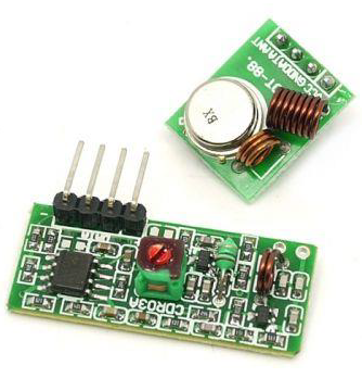
无线发射器和接收器模块工作在315 Mhz。它们可以轻松地装入面包板,并可很好的与微控制器配合使用,创建一个非常简单的无线数据链路。使用一对发射器和接收器,模块将只能单向传输数据,因此,你将需要两对(不同频率)作为发射器/接收器对。
注意 - 这些模块是任意的,并会接收相当大量的噪音。发射器和接收器都在共同的频率下工作,并且没有ID。

你将需要以下组件:
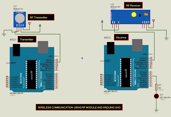
按照电路图进行连接,如下图所示。

在计算机上打开Arduino IDE软件。使用Arduino语言进行编码控制你的电路。通过单击“New”打开一个新的草图文件。

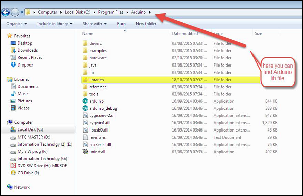
注意 - 你必须在Arduino库文件中包含键盘库。将VirtualWire.lib文件复制并粘贴到库文件夹中,如下面屏幕截图的高亮部分所示。

//simple Tx on pin D12
#include <VirtualWire.h>
char *controller;

void setup() {
   pinMode(13,OUTPUT);
   vw_set_ptt_inverted(true);
   vw_set_tx_pin(12);
   vw_setup(4000);// speed of data transfer Kbps
}

void loop() {
   controller="1" ;
   vw_send((uint8_t *)controller, strlen(controller));
   vw_wait_tx(); // Wait until the whole message is gone
   digitalWrite(13,1);
   delay(2000);
   controller="0" ;
   vw_send((uint8_t *)controller, strlen(controller));
   vw_wait_tx(); // Wait until the whole message is gone
   digitalWrite(13,0);
   delay(2000);
}这是一个简单的代码。首先发送字符“1”,两秒后发送字符“0”,以此类推。
//simple Rx on pin D12
#include <VirtualWire.h>

void setup() {
   vw_set_ptt_inverted(true); // Required for DR3100
   vw_set_rx_pin(12);
   vw_setup(4000); // Bits per sec
   pinMode(5, OUTPUT);
   vw_rx_start(); // Start the receiver PLL running
}

void loop() {
   uint8_t buf[VW_MAX_MESSAGE_LEN];
   uint8_t buflen = VW_MAX_MESSAGE_LEN;
   if (vw_get_message(buf, &buflen)) // Non-blocking {
      if(buf[0]=='1') {
         digitalWrite(5,1);
      }
      if(buf[0]=='0') {
         digitalWrite(5,0);
      }
   }
}当接收到字符“1”时,连接到Arduino板上引脚5的LED亮起,当接收到字符“0”时,LED熄灭。